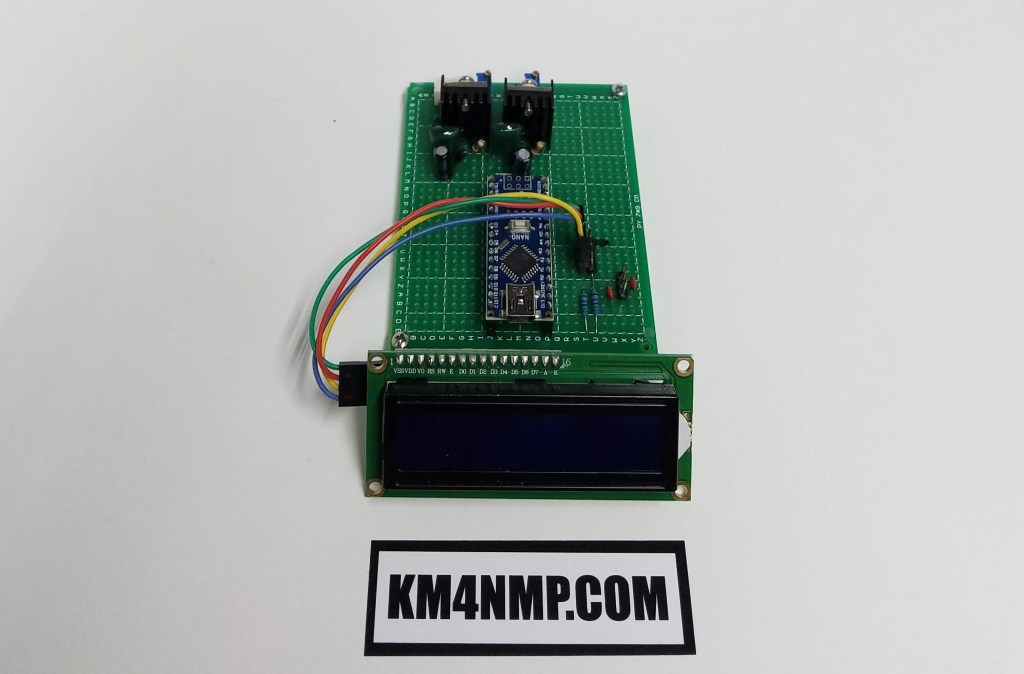
For today’s post, I wanted to start working on an Arduino Based Voltage Monitoring System for my Solar controller. The controller I use has the ability to show voltages but it can only show one at a time. The Arduino Nano will be used to sample and display voltages.

The same basic setup as the SWR bridge post will be used. Two power regulators will be used to step the voltage down from 12v to 5v. This helps with heat dissipation. Three voltages will be sampled with this unit, Solar input Battery and Controller feed voltages. A voltage divider is used to bring the voltage sampled down to a safe voltage for the Arduino to read. Each reading will be displayed on the LCD display.

Since I have not had time to fully construct the Voltage Monitor sketch testing is being done with the test setup from the SWR Bridge. The setup will be replicated on another PCB and the voltage divider added. A potentiometer may be used to adjust the resistance values of the voltage dividers. As this project progress’s updates will be made.
Links
https://km4nmp.com/2020/02/29/testing-the-kitsandparts-com-swr-bridge-with-the-arduino-nano/
https://km4nmp.com/km4nmp/projects/
Latest Posts
- 2:1 Balun For 2m/6m
- 1:1 Choke For 2m and 6m
- 2m Delta Loop Ver 2
- 2m Delta Loop
- Finishing The 6m Delta Loop With 2:1 Balun


4 thoughts on “Arduino Based Voltage Monitoring For the Solar System.”