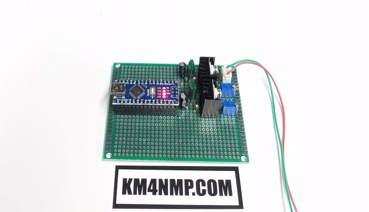
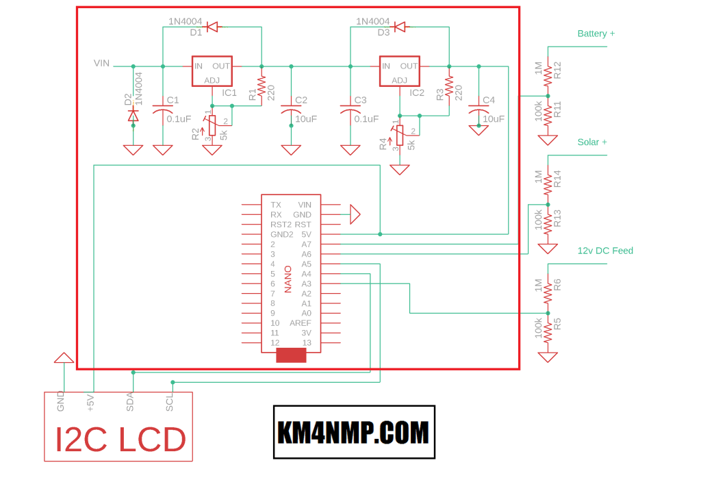
Today, we will start building the Solar Power Monitor. In this post, we mount the power regulators and Arduino Nano to the PCB. Since the power monitor does not require a lot of power, two LM317 adjustable regulators are used.
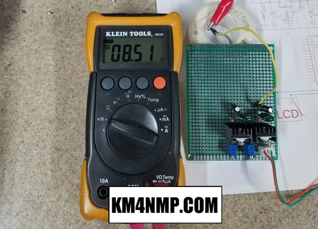
Once the regulators have been mounted, their voltage needs to be adjusted. I set the first regulator to 8.5V. This is half the total voltage drop needed for 5V.
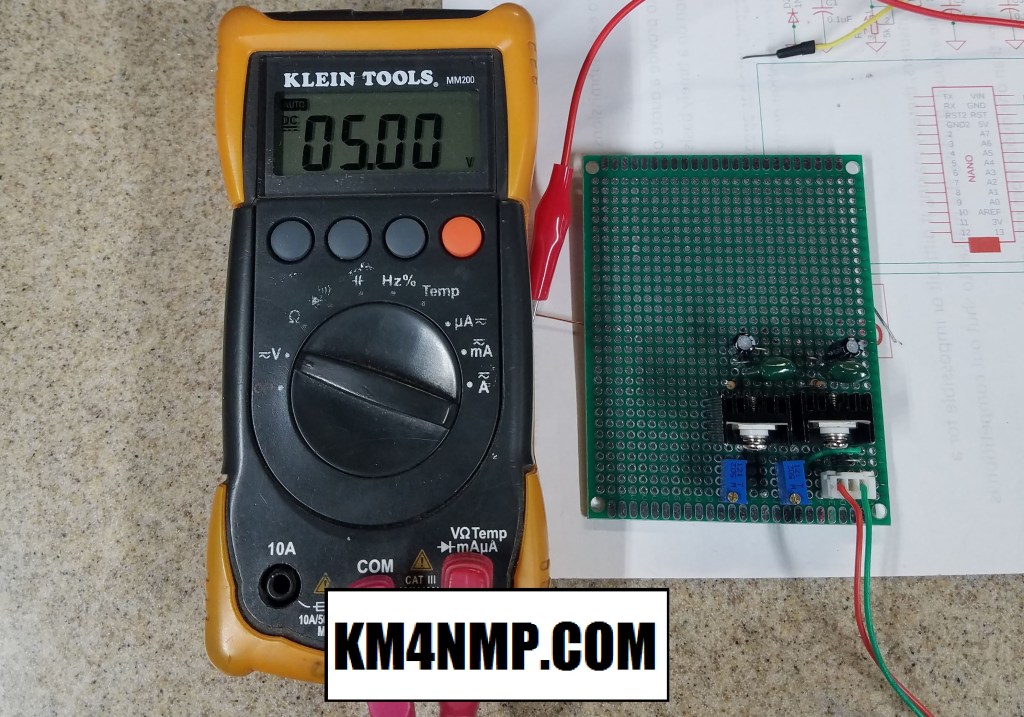
The second regulator is adjusted to 5V. After the voltages are set the Arduino Nano can be mounted.
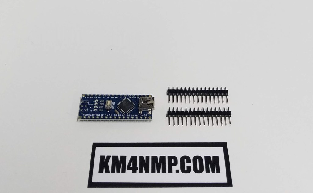
The pins supplied with the nano are used with a female connector on the PCB so the Nano can be removed easily. This makes it easy to remove for reprogramming or replacing.

To verify the Arduino Nano was operating, the sample blink sketch was loaded. In our next post an LCD screen and the voltage dividers will be assembled.
Links
https://km4nmp.com/2020/04/18/arduino-based-voltage-monitoring-for-the-solar-system/
https://km4nmp.com/2020/02/29/testing-the-kitsandparts-com-swr-bridge-with-the-arduino-nano/
Latest Posts
- 2:1 Balun For 2m/6m
- 1:1 Choke For 2m and 6m
- 2m Delta Loop Ver 2
- 2m Delta Loop
- Finishing The 6m Delta Loop With 2:1 Balun


3 thoughts on “Power Regulator And Arduino Nano For The Solar Power Monitor.”