
In this post, the Solar Voltage Monitor will be tested with a solar system. Since this is testing in the lab, the electronics will be mounted to a backboard. Once testing is complete, an enclosure will be designed to provide more protection.
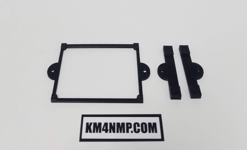
Basic mounting brackets with mounting holes were 3d printed for the electronics. Sheet rock screws will be used to attach the brackets to the plywood backboard.
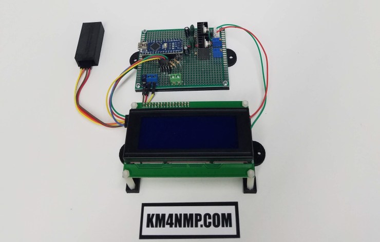
The LCD screen is mounted on stand offs to bring it away from the backboard a little. This makes it easier to connect the interface cable and provides plenty of clearance for the I2C board.
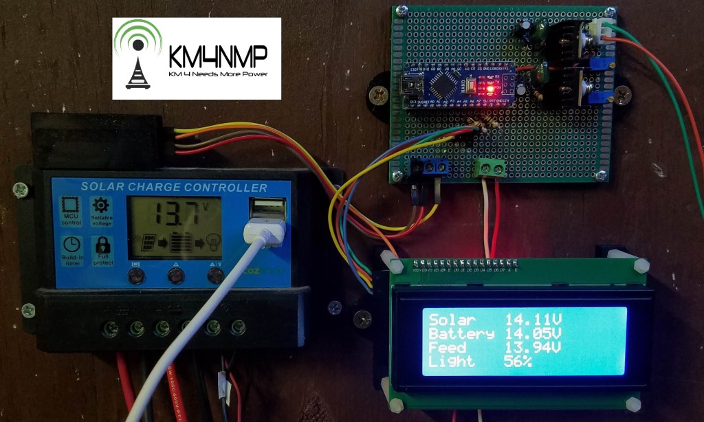
Connecting to the Solar controller was easy. Power for the Solar Monitor is connected to the voltage out of the controller. Wire is installed to sample the battery and solar panel voltage. The Solar Voltage Monitor will stay connected to the test solar set up for a couple weeks. Once testing is complete and updated, post will be made.
Links
https://km4nmp.com/2020/04/26/a-light-level-sensor-for-the-solar-voltage-monitor/
https://km4nmp.com/2020/04/19/power-regulator-and-arduino-nano-for-the-solar-power-monitor/
https://km4nmp.com/2020/04/18/arduino-based-voltage-monitoring-for-the-solar-system/
https://km4nmp.com/km4nmp/projects/
Latest Posts
- 2:1 Balun For 2m/6m
- 1:1 Choke For 2m and 6m
- 2m Delta Loop Ver 2
- 2m Delta Loop
- Finishing The 6m Delta Loop With 2:1 Balun

