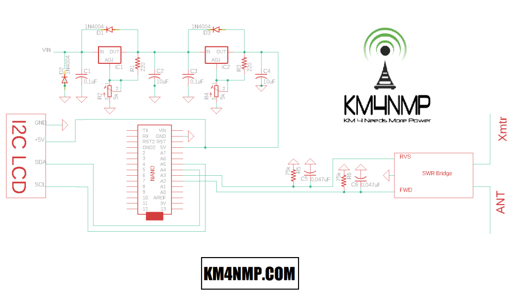
In this post, we will be doing basic testing of the KitsAndParts.com SWR Bridge. The Arduino Nano put together in our last post will be used for testing. A basic program was written to read the forward and reverse voltages with analog pins 2 and 3. To make testing easier, an LCD screen was added to the test setup.
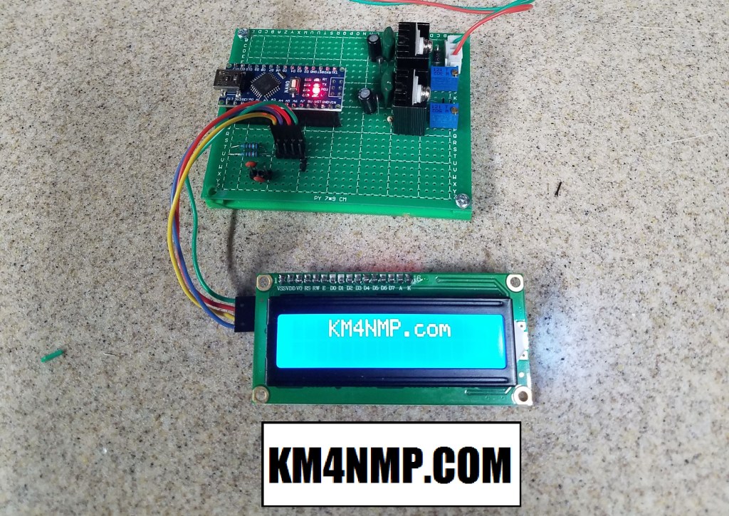
The LCD screen used is 16 x 2 and connected using I2C. The library for the LCD has been used in multiple projects and works well. A link has been placed in the Arduino sketch for the website to download the library.
// SWR Bridge Test Sketch 2/28/20
//https://KM4NMP.com/
//For the I2C LCD library used and installation instructions use link below
//https://randomnerdtutorials.com/esp32-esp8266-i2c-lcd-arduino-ide/


#include <LiquidCrystal_I2C.h>

LiquidCrystal_I2C lcd(0x27,16,2);  // set the LCD address to 0x27 for a 16 chars and 2 line display

void setup()
{
  lcd.init();                      // initialize the lcd
  lcd.backlight();
  lcd.setCursor(3,0);
  lcd.print("KM4NMP.com");
  delay(1500);
  lcd.clear ();
}


void loop()
{
  int FWDsensorValue = analogRead(A2);
  int RVSsensorValue = analogRead(A3);
  float FWDvoltage = FWDsensorValue * (5.0 / 1023.0);
  float RVSvoltage = RVSsensorValue * (5.0 / 1023.0);
  lcd.setCursor(0,0);
  lcd.print("FWD ");
  lcd.print(FWDvoltage);
  lcd.setCursor(0,1);
  lcd.print("RVS ");
  lcd.print(RVSvoltage);
}
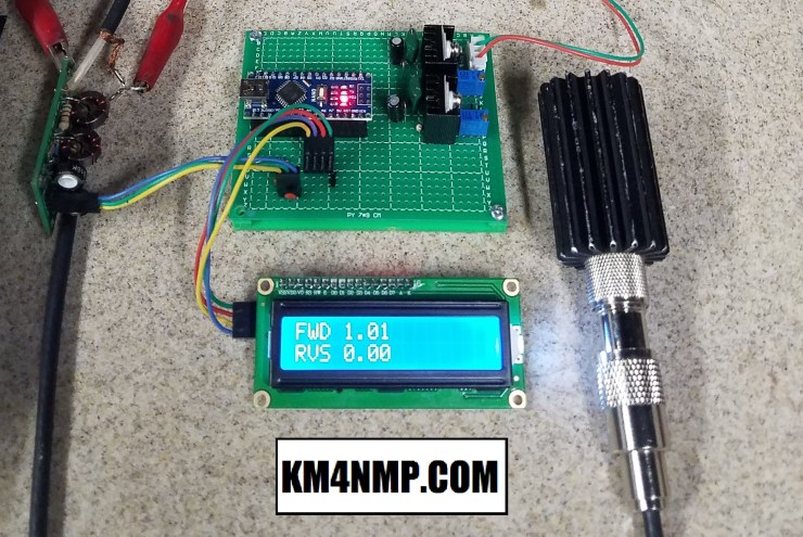
The Sketch is very basic. The Arduino will read the values on the Forward and Reverse pins and display the calculated voltage on the LCD screen.

Testing was first done with the Yaesu FT-891 at 5 W to verify operation. To make it easier to document for this post, the Ubitx V5 was connected. A good dummy load is connected to the RF outside of the SWR Bridge. Once connected, the transmitter was activated with a straight key. This should keep the output power at a constant level. While transmitting the Forward voltage showed a constant 1 volt and did not fluctuate. The Reverse voltage stayed 0 volts. Since the dummy load Tested 1:1 SWR this was expected.
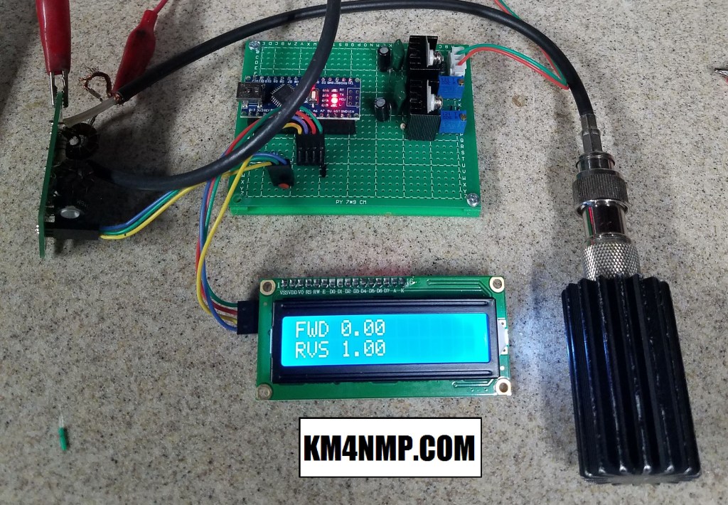
To verify the Reverse voltage is working properly, the connections to the RF in and out were swapped. Without any adjustments to the SWR bridge, the Reverse voltage reading was very close to the Forward voltage reading.
Both SWR Bridges from KitsAndParts.com were tested and are working good. The first project that will be done with the SWR bridges will be installing one in the Ubitx V5. In our next post, we will prepare the Ubitx for the SWR Bridge.
Links
https://randomnerdtutorials.com/esp32-esp8266-i2c-lcd-arduino-ide/
https://km4nmp.com/2020/02/23/connecting-the-swr-bridge-for-testing/
https://km4nmp.com/2020/02/16/assembling-the-kitsandparts-com-swr-bridge-kit/
https://ubitx.net/category/hardware/swr-meter/
https://km4nmp.com/km4nmp/projects/
Latest Posts
- 2:1 Balun For 2m/6m
- 1:1 Choke For 2m and 6m
- 2m Delta Loop Ver 2
- 2m Delta Loop
- Finishing The 6m Delta Loop With 2:1 Balun


2 thoughts on “Testing The KitsAndParts.com SWR Bridge With the Arduino NANO”