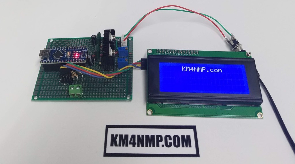
Today, we will build the voltage dividers and connect the LCD screen to the Solar Voltage Monitor. The LCD screen will be connected using I2C. Voltage dividers capable of 55V are used to sample the voltages from the solar power controller. This provides a little protection for the Arduino Nano pins. Battery and solar panel voltages should not get close to this limit.


Since the Solar Power Monitor will be powered by the solar controller, the feed voltage divider was connected to the “Positive In” on the first voltage regulator. The Solar Voltage and Battery Voltage have screw terminals for there connection.

Originally a 2 x 16 LCD screen was going to be used for this project. While gathering parts, I found a nice 4 x 20 LCD at the back of the parts bin. A I2C module is used to reduce the amount of pins required to operate the screen. They also makes projects look much cleaner.
//Solar Power Monitor
//https://KM4NMP.com/
//For the I2C LCD library used and installation instructions use link below
//https://randomnerdtutorials.com/esp32-esp8266-i2c-lcd-arduino-ide/


#include <LiquidCrystal_I2C.h>

LiquidCrystal_I2C lcd(0x27,20,4);  // set the LCD address to 0x27 for a 20 chars and 4 line display

void setup()
{
  lcd.init();
  lcd.backlight();
  lcd.setCursor(5,0);
  lcd.print("KM4NMP.com");
  lcd.setCursor(0,1);
  lcd.print("Solar Power Monitor");
  delay(2000);
  lcd.clear ();
}


void loop()
{
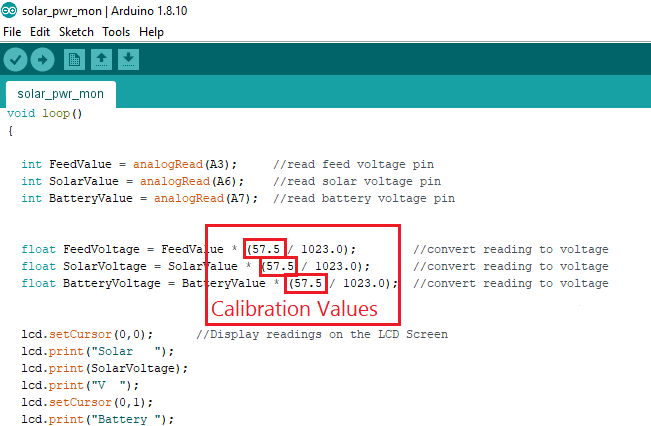
int FeedValue = analogRead(A3);     //read feed voltage pin
  int SolarValue = analogRead(A6);    //read solar voltage pin
  int BatteryValue = analogRead(A7);  //read battery voltage pin

  float FeedVoltage = FeedValue * (57.5 / 1023.0);        //convert reading to voltage
  float SolarVoltage = SolarValue * (57.5 / 1023.0);      //convert reading to voltage
  float BatteryVoltage = BatteryValue * (57.5 / 1023.0);  //convert reading to voltage


  lcd.setCursor(0,0);      //Display readings on the LCD Screen
  lcd.print("Solar   ");
  lcd.print(SolarVoltage);
  lcd.print("V  ");
  lcd.setCursor(0,1);
  lcd.print("Battery ");
  lcd.print(BatteryVoltage);
  lcd.print("V  ");
  lcd.setCursor(0,2);
  lcd.print("Feed    ");
  lcd.print(FeedVoltage);
  lcd.print("V  ");

  delay(1000);
}
This sketch is very basic for testing. The voltage is calibrated by adjusting the value divided by 1023. This value will vary depending on how accurate the resistors are in the voltage dividers. To calibrate set the value to 55 and connect a stable voltage source. Measure the source voltage with a good multimeter. Compare the voltage displayed with the reading taken with the multimeter. If the voltage is low gradually increase the value until the readings match. If the voltage displayed is high gradually decrease the value until it matches the reading from the multimeter. In my case, 57.5 was used.
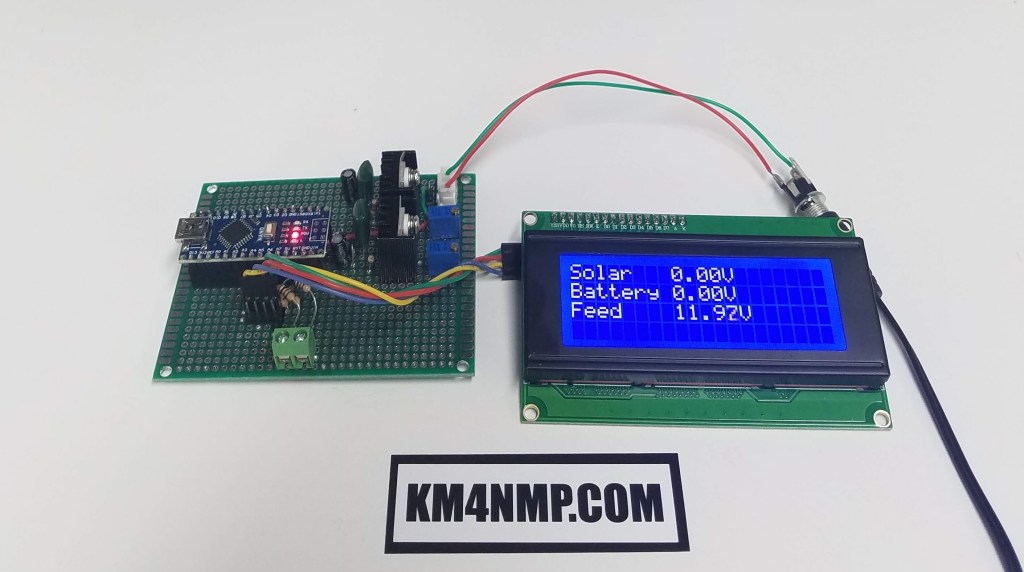
The Solar Voltage Monitor is almost ready to be mounted into an enclosure and start field testing. There is at least one more addition to this project before testing though. A light level reading will be added in our next post.
Links
https://km4nmp.com/2020/04/19/power-regulator-and-arduino-nano-for-the-solar-power-monitor/
https://km4nmp.com/2020/04/18/arduino-based-voltage-monitoring-for-the-solar-system/
https://km4nmp.com/km4nmp/projects/
Latest Posts
- 2:1 Balun For 2m/6m
- 1:1 Choke For 2m and 6m
- 2m Delta Loop Ver 2
- 2m Delta Loop
- Finishing The 6m Delta Loop With 2:1 Balun

