
When monitoring a solar system, it is nice to know when the sun is shining and how much. In this post, we will add a light sensor to the Solar Voltage Monitor. Once complete, the sensor can be placed next to the solar panel and monitor the light level.

A basic light sensor module will be used to detect light levels. A photo-resistor was going to be used originally, but I had this module already and decided to put it to use. When the sensor has no light present, the analog pin puts out 5v. If the sensor receives the maximum amount of light that can be detected, the output voltage is zero. The digital output on the module is not used for this project.
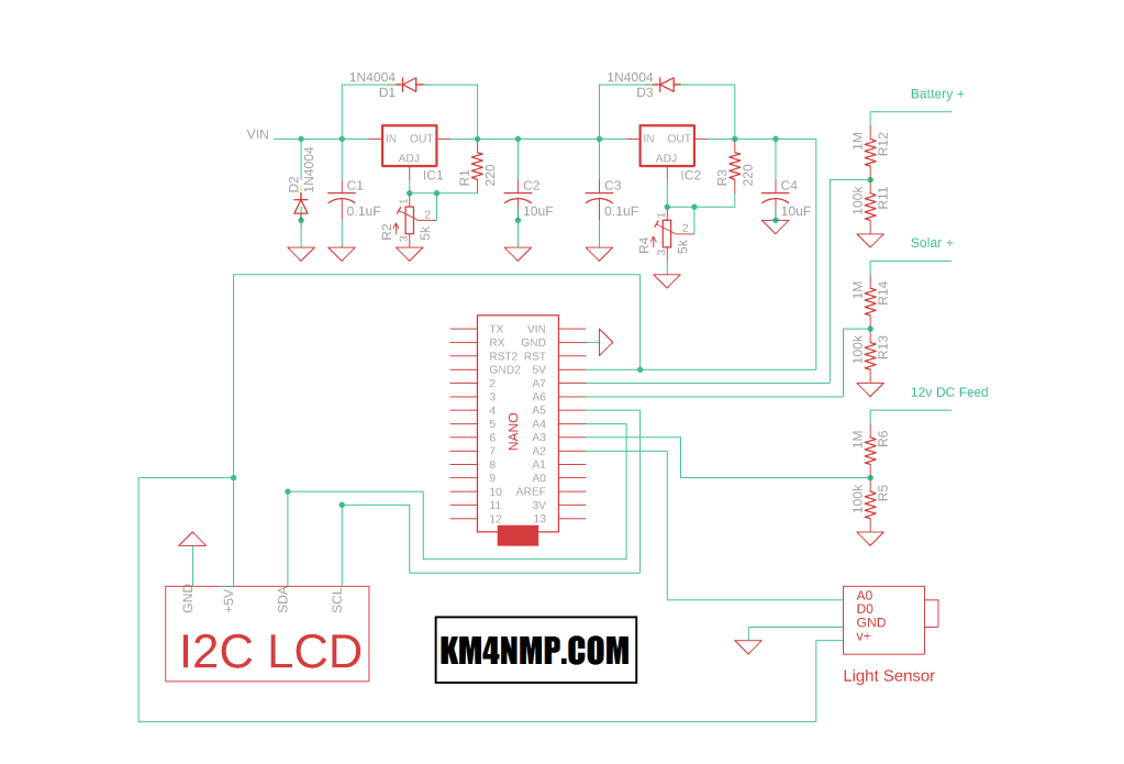
Connecting the module is easy. Simply power the module with 5v and connect the analog output pin to the Nano analog input pin.
//Solar Power Monitor
//https://KM4NMP.com/
//For the I2C LCD library used and installation instructions use link below
//https://randomnerdtutorials.com/esp32-esp8266-i2c-lcd-arduino-ide/


#include <LiquidCrystal_I2C.h>

LiquidCrystal_I2C lcd(0x27,20,4);  // set the LCD address to 0x27 for a 20 chars and 4 line display

void setup()
{
  lcd.init();
  lcd.backlight();
  lcd.setCursor(5,0);
  lcd.print("KM4NMP.com");
  lcd.setCursor(0,1);
  lcd.print("Solar Power Monitor");
  delay(2000);
  lcd.clear ();
}


void loop()
{

  int FeedValue = analogRead(A3);     //read feed voltage pin
  int SolarValue = analogRead(A6);    //read solar voltage pin
  int BatteryValue = analogRead(A7);  //read battery voltage pin
  int LightValue = analogRead(A2);    //read light level pin
  float FeedVoltage = FeedValue * (57.5 / 1023.0);        //convert reading to voltage
  float SolarVoltage = SolarValue * (57.5 / 1023.0);      //convert reading to voltage
  float BatteryVoltage = BatteryValue * (57.5 / 1023.0);  //convert reading to voltage
  int LightPercent = 100 - LightValue * (100.0 / 1023.0); //convert reading to ligh level

  lcd.setCursor(0,0);      //Display readings on the LCD Screen
  lcd.print("Solar   ");
  lcd.print(SolarVoltage);
  lcd.print("V  ");
  lcd.setCursor(0,1);
  lcd.print("Battery ");
  lcd.print(BatteryVoltage);
  lcd.print("V  ");
  lcd.setCursor(0,2);
  lcd.print("Feed    ");
  lcd.print(FeedVoltage);
  lcd.print("V  ");
  lcd.setCursor(0,3);
  lcd.print("Light   ");
  lcd.print( LightPercent);
  lcd.print("%  ");
  delay(1000);
}

Since I decided to use the 4 x 20 LCD screen, there was an extra line to display the light level. The level displayed is based off the capability of the module used. 0% of light would be 5 volts and 100% light would be 0 volts. At some point, I may try to convert this to a standard unit of measurement for light but this will work testing purposes.

After basic testing is complete, the light module will be installed in an enclosure so it can be mounted remotely. Wire screw terminals were used for connections on the main board. The Solar Voltage Monitor is now ready for basic testing. As this project is tested updates will be made.
Links
https://km4nmp.com/2020/04/19/power-regulator-and-arduino-nano-for-the-solar-power-monitor/
https://km4nmp.com/2020/04/18/arduino-based-voltage-monitoring-for-the-solar-system/
https://km4nmp.com/km4nmp/projects/
Latest Posts
- 2:1 Balun For 2m/6m
- 1:1 Choke For 2m and 6m
- 2m Delta Loop Ver 2
- 2m Delta Loop
- Finishing The 6m Delta Loop With 2:1 Balun


1 thought on “A Light Level Sensor For The Solar Voltage Monitor.”