
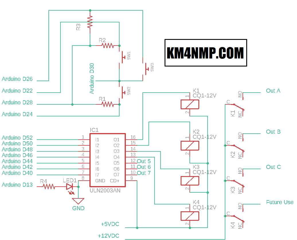
This week, we added our 12 volts to the relays and made a terminal board. This will be used to activate the antenna switch. The switch does not consume a lot of power, so we will use the same 12v that is powering the 5 volt regulator.
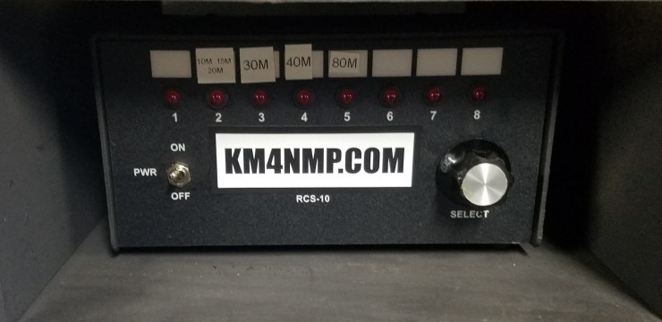
For testing, Connect 3 LEDs to the outputs. As you change antennas the LED pattern should change. The RCS-10 documentation has a table that shows the relays that activate with each antenna. Once tested you can put this project in an enclosure. I will be adding more features to this project and will put it in an enclosure after they are complete.
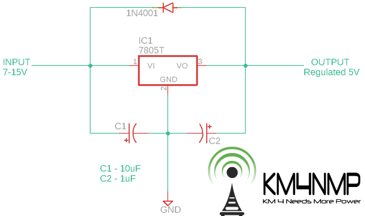
Since the onboard power regulator is not capable of a lot of power, A 7805 power regulator is being used to power the project. When this regulator is connected to 12vdc it produces a good amount of heat. Make sure to put a decent heatsink on the regulator.
/*Arduino Mega RCS-10 Control
  https://MacarrLabs.com/
  https://KM4NMP.com/
  Author: Matthew Carr, Macarr Labs LLC 6/8/19
  Arduino Mega Sketch
*/
//Libraries
#include <Wire.h>
#include <LiquidCrystal_I2C.h>

LiquidCrystal_I2C lcd(0x27, 2, 1, 0, 4, 5, 6, 7, 3, POSITIVE);  // Set the LCD I2C address

const int UpButtonPin = 22;  //set up button pin
int UpButtonPinState = 0; //up button pin state
const int DownButtonPin = 24;  //set down button pin
int DownButtonPinState = 0;
const int OutputA = 52;  //set output a pin
const int OutputB = 50;  //set output b pin
const int OutputC = 48;  //set output c pin
int RelayNumber = 1;
const int ButtonPwrNegPin = 28; //set pin for button negative
const int ButtonPwrPlusPin = 30; //set pin for button positive

void setup() {
  lcd.begin(16,2); //Start LCD
  lcd.backlight(); //Turn LCD Backlight on

  pinMode(ButtonPwrNegPin, OUTPUT);  //initialize the ButtonPwrNegPin as an output
  pinMode(ButtonPwrPlusPin, OUTPUT);  //initialize the ButtonPwrPlusPin as an output
  pinMode(UpButtonPin, INPUT);  //initialize the UpButtonPin as an input
  pinMode(DownButtonPin, INPUT);  //initialize the DownButtonPin as an input
  pinMode(OutputA, OUTPUT);  //initialize the Output A pin as an output
  pinMode(OutputB, OUTPUT);  //initialize the Output B pin as an output
  pinMode(OutputC, OUTPUT);  //initialize the Output C pin as an output

  digitalWrite(ButtonPwrPlusPin, HIGH);
  digitalWrite(ButtonPwrNegPin, LOW);

 lcd.setCursor(0,0);
 lcd.print(" MACARRLABS.COM");
 lcd.setCursor(0,1);
 lcd.print("   KM4NMP.COM");
 delay(3000);
 lcd.clear();
}

void loop() {
   //check button states
  UpButtonPinState = digitalRead(UpButtonPin);
  DownButtonPinState = digitalRead(DownButtonPin);

  if(UpButtonPinState == HIGH) {
    RelayNumber = RelayNumber + 1;
  }
  if(DownButtonPinState == HIGH) {
    RelayNumber = RelayNumber - 1;
  }
  if(RelayNumber > 8) {  //put a max of 3 for relay number
    RelayNumber = 8;
  }
  if(RelayNumber < 1) {  //put a min of 1 for relay number
    RelayNumber = 1;
  }

  //check relay number and activate outputs according to number
if(RelayNumber == 1) {
  lcd.setCursor(0,0);
  lcd.print("Antenna 1");
  digitalWrite(OutputA, LOW);
  digitalWrite(OutputB, LOW);
  digitalWrite(OutputC, LOW);
  }
if(RelayNumber == 2) {
  digitalWrite(OutputA, HIGH);
  digitalWrite(OutputB, LOW);
  digitalWrite(OutputC, LOW);
  lcd.setCursor(0,0);
  lcd.print("Antenna 2");
  }


if(RelayNumber == 3) {
  digitalWrite(OutputA, LOW);
  digitalWrite(OutputB, HIGH);
  digitalWrite(OutputC, LOW);
  lcd.setCursor(0,0);
  lcd.print("Antenna 3");
  }


  if(RelayNumber == 4) {
  digitalWrite(OutputA, HIGH);
  digitalWrite(OutputB, HIGH);
  digitalWrite(OutputC, LOW);
  lcd.setCursor(0,0);
  lcd.print("Antenna 4");
  }

  if(RelayNumber == 5) {
  digitalWrite(OutputA, LOW);
  digitalWrite(OutputB, LOW);
  digitalWrite(OutputC, HIGH);
  lcd.setCursor(0,0);
  lcd.print("Antenna 5");
  }

  if(RelayNumber == 6) {
   digitalWrite(OutputA, HIGH);
  digitalWrite(OutputB, LOW);
  digitalWrite(OutputC, HIGH);
  lcd.setCursor(0,0);
  lcd.print("Antenna 6");
  }

  if(RelayNumber == 7) {
  digitalWrite(OutputA, LOW);
  digitalWrite(OutputB, HIGH);
  digitalWrite(OutputC, HIGH);
  lcd.setCursor(0,0);
  lcd.print("Antenna 7");
  }

  if(RelayNumber == 8) {
  digitalWrite(OutputA, HIGH);
  digitalWrite(OutputB, HIGH);
  digitalWrite(OutputC, HIGH);
  lcd.setCursor(0,0);
  lcd.print("Antenna 8");
  }


 delay(150);

}

Links
https://km4nmp.com/2019/06/08/rcs-10-arduino-controller/
https://km4nmp.com/2019/03/16/ameritron-rcs-10-review/
https://km4nmp.com/2019/05/19/ameritron-rcs-10-fuse-replacement/
https://km4nmp.com/2019/05/25/connecting-the-uln2003-to-the-arduino-mega/
https://km4nmp.com/2019/06/01/arduino-mega-relays-controlled-by-push-buttons/
Latest Posts

2 thoughts on “RCS-10 Arduino Controller PT2”