
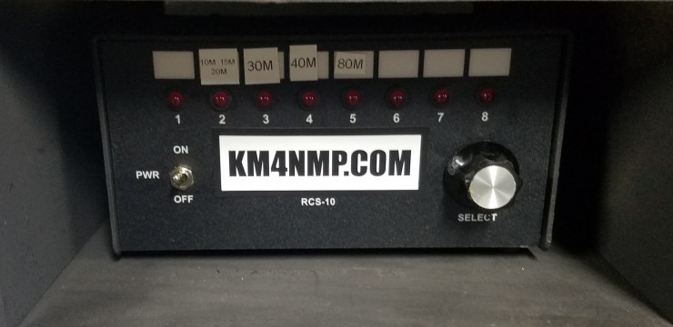
Last week we used an Arduino Mega to control some relays. This week we will be taking our basic setup and use it to control a RCS-10 antenna switch. The relays have been soldered to a project board. LEDs were not used on the project board. If you would like LEDs to remain in your project, it will not cause any issue.
The RCS-10 requires 3 relays to operate. I have added a fourth for future use. The relays are programed according to the table in the product manual. The output to the control head needs 12vdc. this has not been connected to the relays yet. This will be connected and tested in future posts.
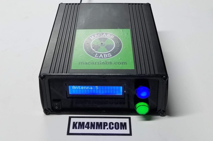
Only 2 buttons are required for this project. The third button in the picture is for future use and is connected to pin D26. Pin D22 is the up button and D24 is the down button. The antenna selected is displayed on the LCD screen.

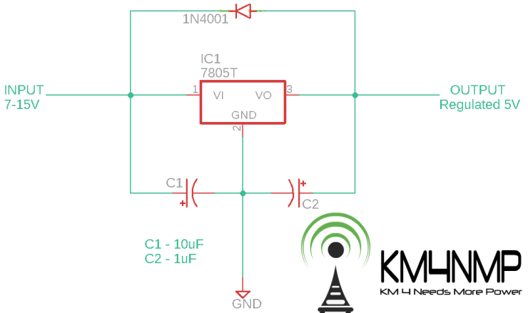
Since the onboard power regulator is not capable of a lot of power, A 7805 power regulator is being used to power the project. When this regulator is connected to 12vdc it produces a good amount of heat. Make sure to put a decent heatsink on the regulator.
/*Arduino Mega RCS-10 Control
  https://MacarrLabs.com/
  https://KM4NMP.com/
  Author: Matthew Carr, Macarr Labs LLC 6/8/19
  Arduino Mega Sketch
*/
//Libraries
#include <Wire.h>
#include <LiquidCrystal_I2C.h>

LiquidCrystal_I2C lcd(0x27, 2, 1, 0, 4, 5, 6, 7, 3, POSITIVE);  // Set the LCD I2C address

const int UpButtonPin = 22;  //set up button pin
int UpButtonPinState = 0; //up button pin state
const int DownButtonPin = 24;  //set down button pin
int DownButtonPinState = 0;
const int OutputA = 52;  //set output a pin
const int OutputB = 50;  //set output b pin
const int OutputC = 48;  //set output c pin
int RelayNumber = 1;
const int ButtonPwrNegPin = 28; //set pin for button negative
const int ButtonPwrPlusPin = 30; //set pin for button positive

void setup() {
  lcd.begin(16,2); //Start LCD
  lcd.backlight(); //Turn LCD Backlight on

  pinMode(ButtonPwrNegPin, OUTPUT);  //initialize the ButtonPwrNegPin as an output
  pinMode(ButtonPwrPlusPin, OUTPUT);  //initialize the ButtonPwrPlusPin as an output
  pinMode(UpButtonPin, INPUT);  //initialize the UpButtonPin as an input
  pinMode(DownButtonPin, INPUT);  //initialize the DownButtonPin as an input
  pinMode(OutputA, OUTPUT);  //initialize the Output A pin as an output
  pinMode(OutputB, OUTPUT);  //initialize the Output B pin as an output
  pinMode(OutputC, OUTPUT);  //initialize the Output C pin as an output

  digitalWrite(ButtonPwrPlusPin, HIGH);
  digitalWrite(ButtonPwrNegPin, LOW);

 lcd.setCursor(0,0);
 lcd.print(" MACARRLABS.COM");
 lcd.setCursor(0,1);
 lcd.print("   KM4NMP.COM");
 delay(3000);
 lcd.clear();
}

void loop() {
   //check button states
  UpButtonPinState = digitalRead(UpButtonPin);
  DownButtonPinState = digitalRead(DownButtonPin);

  if(UpButtonPinState == HIGH) {
    RelayNumber = RelayNumber + 1;
  }
  if(DownButtonPinState == HIGH) {
    RelayNumber = RelayNumber - 1;
  }
  if(RelayNumber > 8) {  //put a max of 3 for relay number
    RelayNumber = 8;
  }
  if(RelayNumber < 1) {  //put a min of 1 for relay number
    RelayNumber = 1;
  }

  //check relay number and activate outputs according to number
if(RelayNumber == 1) {
  lcd.setCursor(0,0);
  lcd.print("Antenna 1");
  digitalWrite(OutputA, LOW);
  digitalWrite(OutputB, LOW);
  digitalWrite(OutputC, LOW);
  }
if(RelayNumber == 2) {
  digitalWrite(OutputA, HIGH);
  digitalWrite(OutputB, LOW);
  digitalWrite(OutputC, LOW);
  lcd.setCursor(0,0);
  lcd.print("Antenna 2");
  }


if(RelayNumber == 3) {
  digitalWrite(OutputA, LOW);
  digitalWrite(OutputB, HIGH);
  digitalWrite(OutputC, LOW);
  lcd.setCursor(0,0);
  lcd.print("Antenna 3");
  }


  if(RelayNumber == 4) {
  digitalWrite(OutputA, HIGH);
  digitalWrite(OutputB, HIGH);
  digitalWrite(OutputC, LOW);
  lcd.setCursor(0,0);
  lcd.print("Antenna 4");
  }

  if(RelayNumber == 5) {
  digitalWrite(OutputA, LOW);
  digitalWrite(OutputB, LOW);
  digitalWrite(OutputC, HIGH);
  lcd.setCursor(0,0);
  lcd.print("Antenna 5");
  }

  if(RelayNumber == 6) {
   digitalWrite(OutputA, HIGH);
  digitalWrite(OutputB, LOW);
  digitalWrite(OutputC, HIGH);
  lcd.setCursor(0,0);
  lcd.print("Antenna 6");
  }

  if(RelayNumber == 7) {
  digitalWrite(OutputA, LOW);
  digitalWrite(OutputB, HIGH);
  digitalWrite(OutputC, HIGH);
  lcd.setCursor(0,0);
  lcd.print("Antenna 7");
  }

  if(RelayNumber == 8) {
  digitalWrite(OutputA, HIGH);
  digitalWrite(OutputB, HIGH);
  digitalWrite(OutputC, HIGH);
  lcd.setCursor(0,0);
  lcd.print("Antenna 8");
  }


 delay(150);

}

Links
https://km4nmp.com/2019/03/16/ameritron-rcs-10-review/
https://km4nmp.com/2019/05/19/ameritron-rcs-10-fuse-replacement/
https://km4nmp.com/2019/05/25/connecting-the-uln2003-to-the-arduino-mega/
https://km4nmp.com/2019/06/01/arduino-mega-relays-controlled-by-push-buttons/
https://km4nmp.com/2019/12/28/finishing-the-rcs-10-arduino-controller/
https://km4nmp.com/2020/03/01/field-testing-the-rcs-10-arduino-controller/
Latest Posts
- 2:1 Balun For 2m/6m
- 1:1 Choke For 2m and 6m
- 2m Delta Loop Ver 2
- 2m Delta Loop
- Finishing The 6m Delta Loop With 2:1 Balun


4 thoughts on “RCS-10 Arduino Controller”