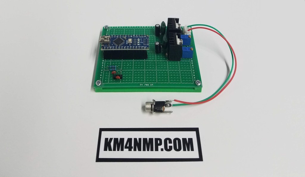
Before connecting the KitsAndParts.com SWR Bridge to the Ubitx, I wanted to do some testing. To do testing, I wanted to use the same type of Arduino that will be added to the Ubitx. The Arduino NANO is the most common board used to add a SWR meter. Since the Ubitx already has a touch screen installed and the updated firmware, once testing is finished this upgrade should be relatively simple.
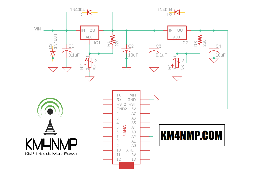
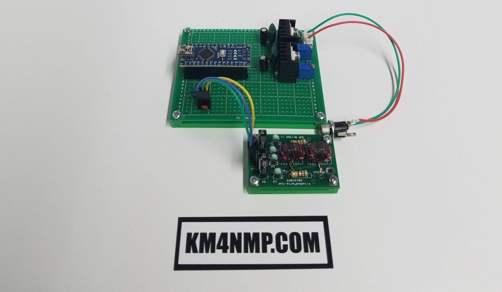
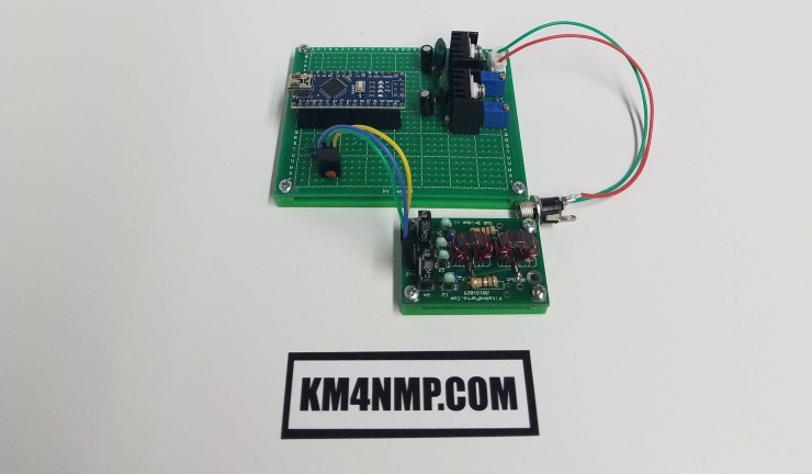
The testing board for the SWR Bridge will serve a dual purpose. Once testing is complete, this board will be used in another project. I wanted to have plenty of power available, so two LM317 are used to provide power regulation. The first LM317 drops the voltage to 9 volts and the second takes it down to 5 volts. This helps the power regulators stay cool and will allow operation without a fan. Both regulators have a good heat sink installed.
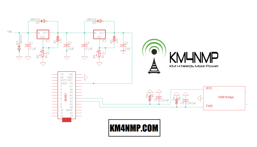
Connection of the SWR Bridge is the similar to what is suggested on several blogs and the Ubitx website. The Ubitx website lists 0.05 uF capacitors for the forward and reverse voltage lines. I did not have any 0.05 uF capacitors, so a 0.047 uF capacitor was substituted. The resistors and capacitors are supposed to drain accumulated charge when no RF is present.
A sketch for testing has not been written yet. For basic testing the readings will be read through the Serial Monitor. A LCD screen may be added to make testing easier.
Testing will be done with the Yaesu FT-891 with low power and the Ubitx. The second SWR bridge with surface mount capacitors will also be tested.
Links
https://km4nmp.com/2020/02/16/assembling-the-kitsandparts-com-swr-bridge-kit/
https://ubitx.net/category/hardware/swr-meter/
Latest Posts
- 2:1 Balun For 2m/6m
- 1:1 Choke For 2m and 6m
- 2m Delta Loop Ver 2
- 2m Delta Loop
- Finishing The 6m Delta Loop With 2:1 Balun


1 thought on “Connecting the SWR Bridge For Testing”