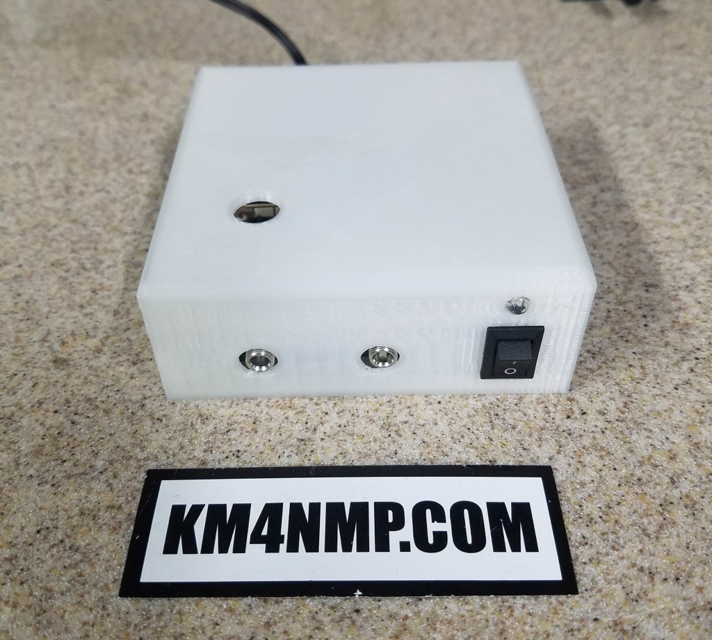
A couple weeks ago we made a case for the 40m Pixie. The case works well but I decided a couple changes would be nice. The main addition is the led on the front of the case. It is connected to the power switch to indicate if the power is on. The next change is a second switch. It will be connected to the positive leg of the buzzer so it can be turned off.

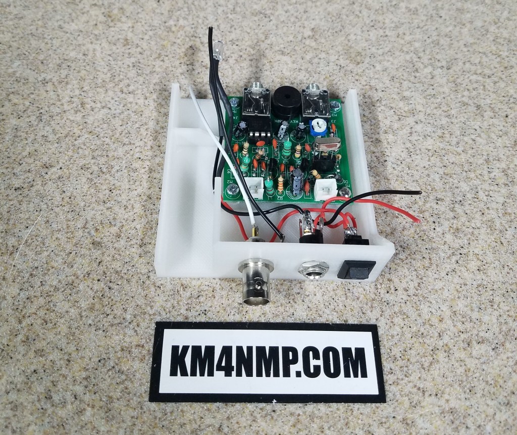
I am using the switch on the back of the unit as the power switch. The led is wired directly to the switch. The dc jack selected has a third terminal that acts as a switch. This gives me the capability to add a 9v battery connector and easily switch between battery and 12v wall adapter.

The led slides into the hole in the front perfectly and friction holds it in place.

The buzzer will be taken off of the PCB and wires soldered in its place. The positive side of the buzzer will go through the switch. The buzzer will be attached to the case with a little hot glue. Another version of this case may be made with an additional led to indicate the pixie being keyed.
Links
https://km4nmp.com/2019/09/04/40m-pixie-case/
https://km4nmp.com/2019/08/03/assembling-the-40m-pixie/
Latest Posts
- 2:1 Balun For 2m/6m
- 1:1 Choke For 2m and 6m
- 2m Delta Loop Ver 2
- 2m Delta Loop
- Finishing The 6m Delta Loop With 2:1 Balun

