
A fellow amateur radio operator asked if I could give them a hand with a project they started. He had a uBITX Transceiver that was assembled and needed to be installed in a case. While installing it in a case, he also wanted to upgrade the display. He chose the Nextion 3.2″ TFT Touch Screen. Macarr Labs printed out all 3d printed parts used in this post.
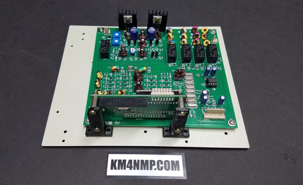
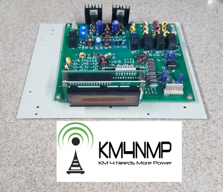
First the main board was mounted to a back plane and the LCD display was removed. Brackets to stabilize the Raduino board were printed out and installed. This will help to maintain a good connection between the boards.

The main enclosure is a reused access control panel enclosure. One advantage of this enclosure is it’s metal. The foot print of the main board also fit very well in the enclosure.


The 3.2″ touch screen was mounted and the wires routed. In another post, we will connect it and load any needed files. There is an access hole in the top of the front bezel for accessing the touch screen SD card. A cover with the owners call sign is being printed to protect the SD card. It is also a nice way to make the radio a little more personal.
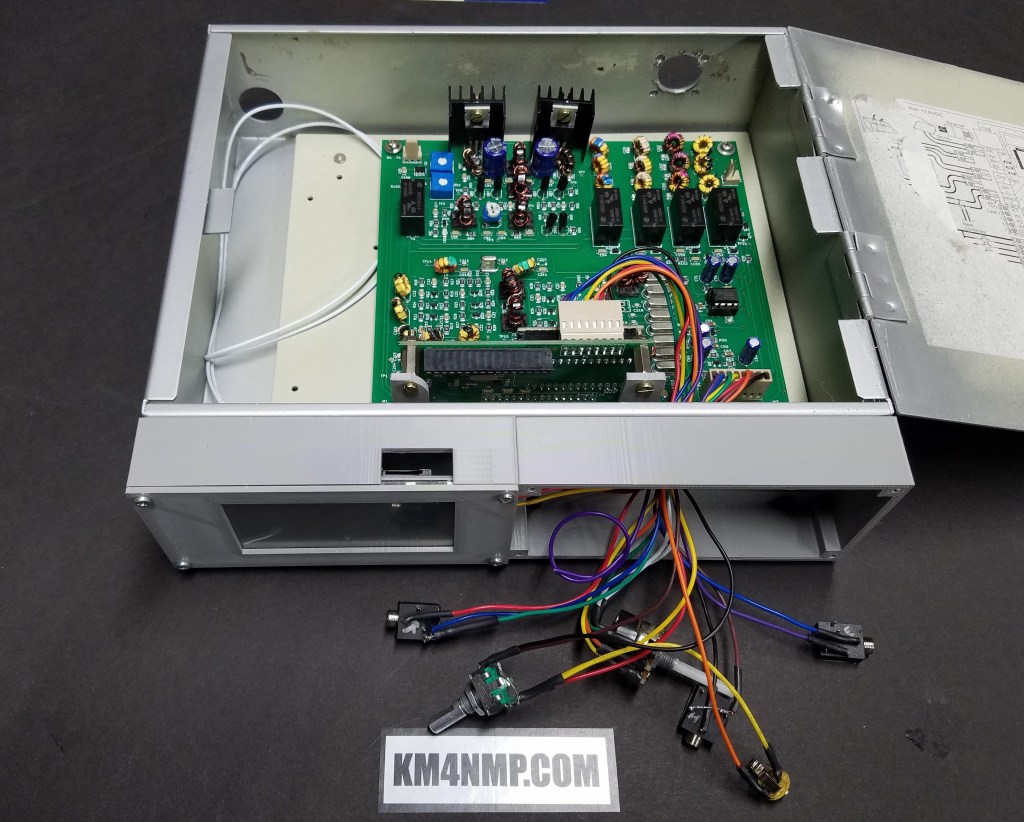
All the wiring was cut as short as possible and routed to the front of the enclosure. I always like to try to keep wiring in projects as neat and short as possible. This helps keep interference out and easier to trouble shoot. Make sure you leave enough slack so you do have issues getting the jacks, potentiometer , and rotary encoder in there hole. Wiring diagram can be found at the HF Signals Website.

A forth jack was added to separate the PTT from the MIC. The order of the jack from left to right is – Headphone, Mic, PTT, and KEY. An internal speaker will be installed in this radio. The head phone jack has been wired so when the headphones are plugged in they bypass the internal speaker.

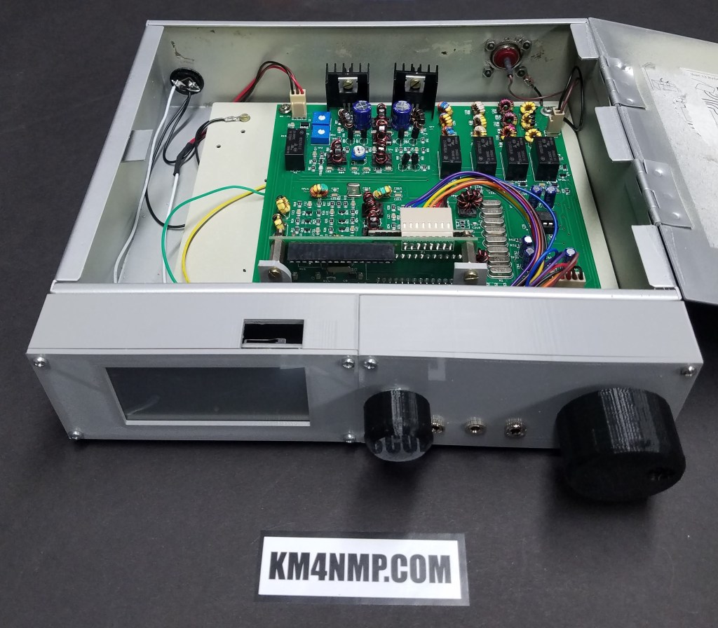
Since the enclosure is metal, the negative side of the power bonded to the cases with a 18 awg wire. This helps reduce the chance of a ground loop. The wire is soldered into the ring terminal to make sure it has a very good connection. Make sure to clean and remove any paint from the connection point.

A few more details will be added to the case, to give it more personality and break up the grey a little. Once the files for the TFT screen are loaded and some testing done, another post will be made.
Links
Latest Post
- 2:1 Balun For 2m/6m
- 1:1 Choke For 2m and 6m
- 2m Delta Loop Ver 2
- 2m Delta Loop
- Finishing The 6m Delta Loop With 2:1 Balun


This is a custom case build that resembles a military radio onboard a naval/cutter vessel! Looks and added functions will make operations easy and fun! Thank you!
LikeLiked by 1 person