
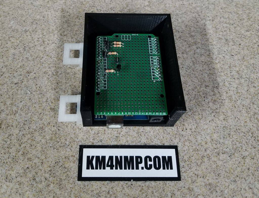
The Arduino Basic Keyer was an easy project to build and program. Since the original project was built on a solderless bread board, I wanted to make it more permanent. Today we will rebuild the Arduino Basic Keyer using a project board. A port for a straight key will also be added.

To minimize connections, Pin 5 will be set low and used as a ground for the paddle and straight key. Pin 3 and 7 are set high and used for the paddle and straight key instead of 5 volts. Pin 6 is used for the straight key input.


The case and DINN mounts were provided by Macarr Labs.

3.5 mm jacks are used to connect the straight key and paddle. The straight key is on the left and paddle on the right.
Arduino Keyer with Straight Key Sketch
//Arduino Keyer with Straight Key 9/27/19
//https://MacarrLabs.com/
//https://KM4NMP.com/
//Author Matthew Carr KM4NMP 9/28/19
//common plug pinouts are:
//  Tip – left lever, or left side of single lever, normally Dot
//  Ring – right lever, or right side of single lever, normally Dash
//  Shaft – common

int LeftPin = 2;  //left paddle push pin
int RightPin = 3; //right paddle push pin
int LeftPinState = 0;
int RightPinState = 0;
int StraightkeyState = 0;
int audio = 12;   //audio out pin
int note = 600;   //note pitch change for a different tone
int dotTime;
int dashTime;
int buttonNeg = 5;
int buttonPlus = 4;
int Straightkey = 6;
int StraightkeyPlus = 7;

void setup() {
 Serial.begin(9600);        //for debugging
  pinMode(buttonNeg, OUTPUT);
  pinMode(buttonPlus, OUTPUT);
  pinMode(StraightkeyPlus, OUTPUT);
  digitalWrite(buttonNeg, LOW);
  digitalWrite(buttonPlus, HIGH);
  digitalWrite(StraightkeyPlus, HIGH);
  pinMode(LeftPin, INPUT);   //set pin as input
  pinMode(RightPin, INPUT);  //set pin as input
  pinMode(Straightkey, INPUT);  //set pin as input
  dotTime = 125;             //dot time in milliseconds
  dashTime = dotTime * 3;
}void loop() {
LeftPinState = digitalRead(LeftPin);
RightPinState = digitalRead(RightPin);
StraightkeyState = digitalRead(Straightkey);
if ( StraightkeyState == 1) {
Serial.print("Straight Key active "); //for debugging
Serial.println(StraightkeyState); //for debugging
tone(audio, note);
}
if ( StraightkeyState == 0) {
noTone(audio);
}
if (LeftPinState == 1) {
Serial.print("left "); //for debugging
Serial.println(LeftPinState); //for debugging
tone(audio, note); //start tone
delay(dotTime); //tone length
noTone(audio);
delay(dotTime); //time between tones
}
if (RightPinState == 1) {
Serial.print("Right "); //for debugging
Serial.println(RightPinState); //for debugging
tone(audio, note); //start tone
delay(dashTime); //tone length
noTone(audio);
delay(dotTime); //time between tones
}
}
Links
https://km4nmp.com/2019/06/09/basic-arduino-keyer/
https://km4nmp.com/2019/06/16/arduino-keyer-with-adjustable-speed-and-lcd/
Latest Posts
- 2:1 Balun For 2m/6m
- 1:1 Choke For 2m and 6m
- 2m Delta Loop Ver 2
- 2m Delta Loop
- Finishing The 6m Delta Loop With 2:1 Balun


You can use a single jack for both paddles and straight key. Straight key will have a 2 conductor plug, paddles a 3 conductor tip, ring, and sleeve. So in setup() look for a ground on the ring lead if found assume straight key.
LikeLiked by 1 person
Very true. The main reason for the build is a friend wanted to have both the key and paddle connected at the same time. In a later revision, a pin could be added to the straight key port. With your suggestion, it could detect what is connected and set the mode of operation. Thank you for the input.
LikeLike