
Today the Tram 1400 VHF Base Station Antenna will be installed. The antenna will be mounted on a 1 1/2 inch chain link fence top rail. Three 10 feet sticks of top rail are used as the mast, so the base of the antenna will be at 30 feet. LMR-600 will be used for the feed line. This is a bit overkill but the feed line and connectors are already on hand.
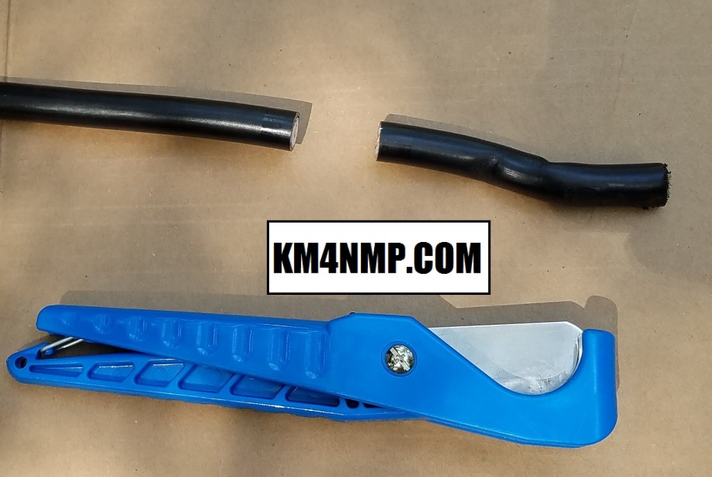
Before the antenna is mounted, the antenna side of the feed line is prepped for a connector. First the cable needs a good flush cut.

The connectors used in this post are clamp style. Before stripping the cable, heat shrink and the compression collar are placed on the cable.
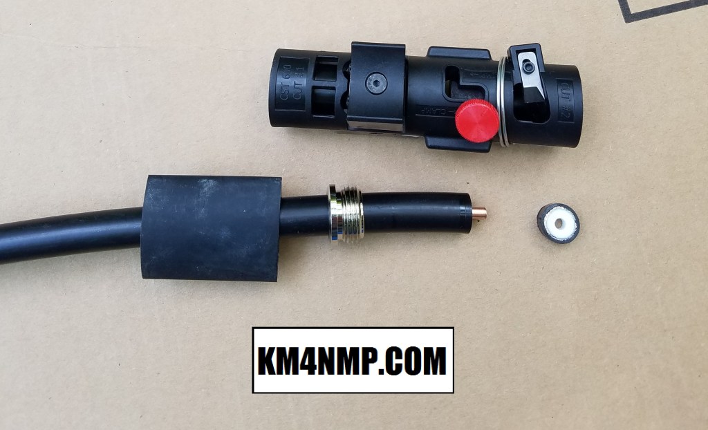
A good cable prep tool makes installing connectors very easy. This tool has 2 cutters to prep the cable. The first cut strips the dielectric and outer jacket off, exposing the center conductor.
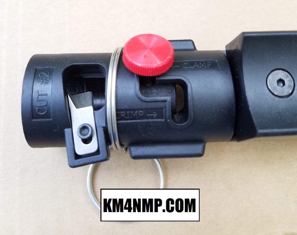
Before making the second cut verify the tool is set properly for the type of connector being used.
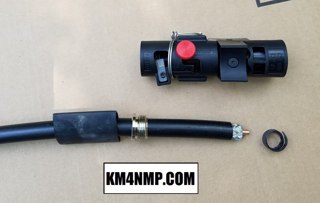
The second cut strips the outer jacket to the proper braid length needed. This is the advantage of using a prep tool. Each cut is precisely the right length and will work well with the connector.

The pin is soldered to the center conductor of the cable. Be careful to not over heat the dielectric and damage it.

After the Center pin is soldered to the center conductor the body of the connector can be installed. I like the thread the connector as much as possible by hand and the finish with an open end or adjustable wrench.
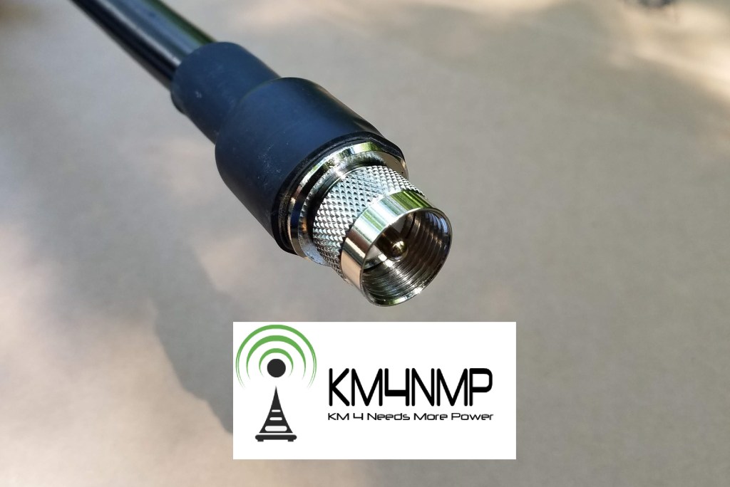
Since this connection is on the antenna side of the feed line, heat shrink is installed on the connector.

Now the feed line is ready we can move on to the antenna. Since the antenna was assembled and tuned in our last post, the antenna was just removed from the test stand and mounted to the mast. The feed line connection at the base of the antenna was taped several layers of high quality electric tape and rubberized tape. Unfortunately I was not able to take pictures of weatherizing the connection. It was done 15 feet on top of a ladder and difficult enough without taking pictures.

After the antenna is placed in its base, the feed line is cable tied to the mast so the weight of the cable does not put extra stress on the connection.
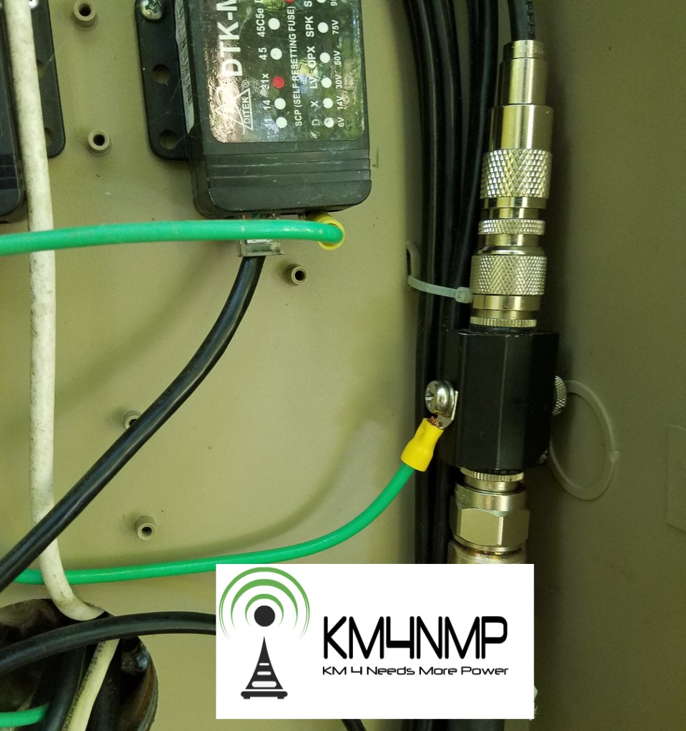
A lighting protection module is installed at the point of entry. A 10 awg ground cable is connected directly to the ground bus bar.


Before connecting the Tram 1400 to the transmitter another SWR test was performed. Results were good and connections to the transmitter were made. Basic testing was done with the transmitter. A local simplex net in my area happened to be running and first impressions are good. More simplex testing will be done to test the limits of the Tram 1400 base station antenna.
Links
https://km4nmp.com/2020/05/03/the-tram-1400-vhf-aluminum-omni-base-station-antenna/
https://km4nmp.com/2019/09/14/rebuilding-the-portable-j-pole/
https://km4nmp.com/2019/07/20/2m-portable-slim-jim-antenna/
https://km4nmp.com/km4nmp/projects/
Latest Posts
- 2:1 Balun For 2m/6m
- 1:1 Choke For 2m and 6m
- 2m Delta Loop Ver 2
- 2m Delta Loop
- Finishing The 6m Delta Loop With 2:1 Balun


1 thought on “Installing The Tram 1400 Base Antenna”